Due to problems I had with LTC3780 boost\buck converter boards and the fact that they are really not designed to be used with adjustable Voltage\Current potentiometers due to the high resistance pots required (the high impedance wires easily pick up stray noise which causes instability), I decided to try the D3806 Boost\Buck converter which has user push-button + LED display. These should be easy to extend to the front panel of a bench PSU as they should be all low-impedance connections.
The LED+button board is on a separate riser PCB and contains a micro-controller. It is supposed to have reasonable ripple\noise output too (TBD).
But is it any good...?
Basic specs:
Sending 10V+ to your 3.3V project is not a good idea!
The length of this spike depends on the load connected. It seems to be putting a short spike into the output capacitors which then take time to drain according to how big a load is connected.
The max voltage of the pulse depends on your input voltage (seems to be approx 1/2 of input voltage).

And then...
I found that my delay circuit reset itself as soon as the D3806 output was enabled! If I pressed the OK button to enable the ouput, the delay circuit would reset - this caused the relay to go off which caused the load to be removed - the delay circuit then switched the relay on again after a few seconds and then this caused it to reset as soon as the load was connected. etc. etc.
Input voltage: 12V
Output voltage: (any - I tried 10V, 12V and 20V)
Load: 52R or greater (the greater the load the larger the surge!)
Method: Enable D3806 output (press OK button)
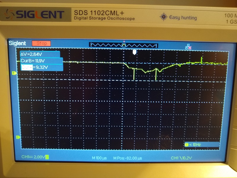
Result: Massive dip on power input - 12V supply dips to 9V
I tried an ATX power supply, a bench switched-mode PSU and a bench linear PSU - all were similary affected.
When I connected a scope to the input terminal of the D3806, I saw that at the instant that the output was enabled, the input supply suddenly dropped (e.g. from 12V to 7V). This is caused by the D3806 MOSFETs turning hard on very quickly and the sudden demand cannot be met by the power supply.
Some power modules have a 'soft start' feature. This means that they don't suddenly demand 10 Amps but gradually increase their power output when a change in load is detected.
If you are using a D3806 on a DC supply with no other devices connected, the sudden power loss will not affect you. However, if you are driving any other circuitry (other power modules, meters, etc.) from the same supply rail, then beware - because all these other devices will see a massive drop in their supply rail when you enable the output of the D3806!
Note: This massive demand can cause fuses to blow even though the load is well within the power limitations of the supply!
So, if you are using an ATX power supply to power the D3806, the solution is to use one 12V output for the D3806 (and any other power module) and the other 12V output for any circuitry which is sensitive to sudden dips!
 |
| D3806 - DC-DC boost\buck converter with potential 38V 6A output. P/N 321510269 |
The LED+button board is on a separate riser PCB and contains a micro-controller. It is supposed to have reasonable ripple\noise output too (TBD).
But is it any good...?
Basic specs:
| Module type | Non-isolated buck module |
| Input voltage | 10V-40V |
| Output current | 0-6A |
| Output voltage | 0-38V |
| Conversion efficiency | Up to 92% |
| Operating frequency | 150KHz |
| Short circuit protection | Constant current |
| Operating temperature | -40°C to + 85°C |
| Control method | Digital control + digital display |
| Voltage regulator / Display resolution | 0.01V |
| Minimum power display resolution | 0.001W |
| Current regulation / Display resolution | 0.001A |
| Minimum capacity display resolution | 0.001AH |
| Output ripple | ≤50mV |
| Weight | 116g |
| Dimensions | 100 x 80 x 21mm (L x W x H) |
I planned to use this with the 12V supply from an ATX power supply (note that the minimum input voltage is 10V for the D3806). I don't expect to be able to get the full 6 Amps at 38V from it though when powered by 12V on the input.
I thought that, if necessary, I could add four new buttons to the front panel of my bench power supply enclosure (I also found that those small buttons on the D3806 were rather hard on my finger tips after using it all day!).
So, after playing with it a few days, what do I think of it? Is it any good as a bench PSU?
- It appears to be reliable and predictable in it's behaviour (once you understand how the poorly documented firmware works).
- It has some useful features such as ten programmable memory settings and it can display Amp-hours and Watts as well as Voltage and Current.
- Once calibrated, the settings\readings are reasonable accurate.
- It has a connector for a 12V fan (untested).
So, this looked like it could be used as a reasonably cheap bench power supply, except I then found these issues which are show-stoppers as far as I am concerned:
- When you apply DC input power, there can be a 4-6V large spike on the output (with or without a load connected).
- When you switch off the DC input power with the output on, there can be a 4-6V large spike on the output (with or without a load connected).
- When you switch off the DC input power with the output off, there can be a 4-10V large spike on the output (with or without a load connected).
- At output voltages above 35V, I could hear 'buzzing' which is not a good sign (so I kept voltages to below 35V to be on the safe side!).
- Accidentally entering calibration mode (F1-F6) when your project\load is connected can blow up your project!
 |
| 1. Switching on input power (output has been set not to switch on) causes 6V pulse on the output (30 Ohm load - 12V input)! |
 |
| 2. Switching off input power when output is at 2V causes an 8V output surge (30 Ohm load - 12V input)! |
 |
| 3. Switching off input power when output is already off causes a 10V output surge (30 Ohm load - 24V input)! |
The length of this spike depends on the load connected. It seems to be putting a short spike into the output capacitors which then take time to drain according to how big a load is connected.
The max voltage of the pulse depends on your input voltage (seems to be approx 1/2 of input voltage).
I see from some blog and YouTube comments that others have been caught by this too and one person listed about 6 projects that he blew-up before he realised what was going on.
Yet again, I have been caught by the lure of badly designed Chinese CR*P!
So the only way to use this module as a cheap bench PSU + ATX power supply would be to connect a large 10A double-pole toggle switch to the output terminals so that you could ensure that your precious project was not connected to it when you switch it on or switch it off. Of course, this assumes that you will remember to use the 'don't blow up my board' switch every single time!
The other alternative might be to use some sort of relay at the output terminals with 10A rated contacts instead of a large toggle switch...
Yet another problem - no 'soft start'!
OK, so I designed and built a simple delay-on/quick-turn-off circuit using a MOSFET and a 5V relay (more on this in a future blog). The circuit worked well, it uses the relay to only connect the output terminals after approx. 1 second after DC power is applied to the D3806. It also turns off the relay as soon as the input voltage drops below about 8V thus ensuring the large voltage spike that appears on the output of the D3806 when the supply is switched off - so the off spike never reaches the output terminals.
And then...
I found that my delay circuit reset itself as soon as the D3806 output was enabled! If I pressed the OK button to enable the ouput, the delay circuit would reset - this caused the relay to go off which caused the load to be removed - the delay circuit then switched the relay on again after a few seconds and then this caused it to reset as soon as the load was connected. etc. etc.
Input voltage: 12V
Output voltage: (any - I tried 10V, 12V and 20V)
Load: 52R or greater (the greater the load the larger the surge!)
Method: Enable D3806 output (press OK button)
Result: Massive dip on power input - 12V supply dips to 9V
I tried an ATX power supply, a bench switched-mode PSU and a bench linear PSU - all were similary affected.
When I connected a scope to the input terminal of the D3806, I saw that at the instant that the output was enabled, the input supply suddenly dropped (e.g. from 12V to 7V). This is caused by the D3806 MOSFETs turning hard on very quickly and the sudden demand cannot be met by the power supply.
Some power modules have a 'soft start' feature. This means that they don't suddenly demand 10 Amps but gradually increase their power output when a change in load is detected.
If you are using a D3806 on a DC supply with no other devices connected, the sudden power loss will not affect you. However, if you are driving any other circuitry (other power modules, meters, etc.) from the same supply rail, then beware - because all these other devices will see a massive drop in their supply rail when you enable the output of the D3806!
Note: This massive demand can cause fuses to blow even though the load is well within the power limitations of the supply!
 |
| ATX supply rail surge |
 |
| Bench PSU supply rail |
ATX PSUs usually have two 12V output rails. One is the large 24-pin mainboard connector and the other supplies the peripherals (SATA/IDE/graphics).
If you do not see '02.00' and '24.00' initially for F1/F3 or '0.200' and '2.800' for F2/F4 then repeat steps 1 and 2 to reset the calibration values and turn power off/on again.
You may need to repeat steps 3-7 again.
Your input power source must be capable of supplying at least 15W of power (2.8A at 5V).
P.S. Apparently there was a revision 2 of this board which fixed the power surge issue a few years ago (from some YouTube comments - not confirmed) but I have no idea what it's part number is. My unit was ordered in November 2019. I contacted Banggood, gave them the P/N and asked about fixes but they just gave me £7 refund and said sorry (i.e. 'yeah we know it's cr*p but we hoped you wouldn't notice!').
My D3806 is: P/N 321510269
I have seen others on various websites -
P/N 32151036
P/N 32151380 (YTube)
P/N 32156738
P/N 32159383
P/N 32159807
P/N 32154724
 |
| The fix: use the other 12V output! |
User Guide for D3806
For those of you who have one of these (or still want to buy one), here are my notes on how to use the buttons on the display panel together with the 'secret' modes.
Basic operation
- 10 memory locations are used to store V+A pairs (Mem0-9).
- By default (in simple mode, Mode 1 - n), Mem-0 stores the current values.
- Standard behaviour is to be able to set V and A only.
- OK button will enable the output and SET button will then turn off the output.
- Holding down OK for 3 seconds will cause the LED display to cycle between different readings.
Tip: Voltages are always displayed with the second digit showing the decimal point, so if that dot is lit - you know its the voltage.
Enable Special Modes
There are three secret modes which can be enabled\disabled to modify the standard behaviour. These modes are enabled/disabled by holding down the OK button before you switch on input power. You will see 0 then 1 then 2 in a cycle. Release the OK button when the mode number that you want to toggle is displayed. If it was 'n' before, it will be set to 'y' and vice versa.
Enabled = y, disabled=n.
Mode 0-y - when the unit is powered on, the output will be immediately enabled.
Mode 1-y - the SET button will cycle through V, A and then also Load (Lo-x) and Save (SA-x) to allow you to load or save 10 saved V/A settings.
The OK button will allow user to view any of V, A, Watts (P) or capacity (C) (holding OK down for 3 seconds causes all four values to be shown with a 3 second delay between each one).
The OK button will allow user to view any of V, A, Watts (P) or capacity (C) (holding OK down for 3 seconds causes all four values to be shown with a 3 second delay between each one).
Mode 2-y - the LEDs will always cycle between V, A, Watts VA (P) and capacity AH (C) with a 3 second interval between each, once the output is enabled.
4 Buttons
Up/Down buttons: Adjusts the value shown on the display.
SET button:
- If output is on, pressing SET turns off the output.
- Can be used to select Volts and Amps and then adjust it using the Up-Down buttons.
- If press SET after adjusting V or A, it will save the current V and A setting (display briefly shows - - -).
- When Mode 1 is enabled, SET button can be used to select V, A, Load V+A setting x (Lo-x) or Save V+A setting x (SA-x). If no Lo-x or SA-x is shown, the current setting will be saved into x=0.
- - - - - denotes the setting has been saved.
OK button:
- Enables the output.
- If pressed again it will display next reading - e.g. Amps (and Power VA and AmpHours depending on Mode selected).
- If held down for 3 seconds, the LEDs will cycle every 3 seconds (e.g. V, A, V, A, etc. or V, A, P, C, V, A, P, C)
- If held whilst input power is applied, you can enable\disable one of the three special modes.
D8036 Calibration procedure
WARNING: Curiously, the calibration menu can be easily accessed without needing to do a 'hold-down-button + power-on' dance, however if entered by mistake, it can cause damage to any project you have connected! If you see - F1 - displayed (or any F1 - F6 number), press SET again to exit the mode.
First:
- Disconnect any project or load on the output terminals. If you have a VA meter connected, ensure that the small black meter wire is NOT connected.
- Disconnect the input power. Now hold in OK button and switch on power - see 0 -1 - 2 cycle - when 0, release the OK button - repeat this until --n- is shown. Do this for 0, 1 and 2.
Calibration:
You will just need a Digital Volt Meter (DVM) which can accurately measure Volts and measure a maximum current of 3A or more. Do not connect any load (except high-impedance meters).
Calibration should be done when in the final enclosure + normal cooling/running conditions.
F1 adjusts the voltage measurement (ADC) so the D3608 can accurately measure voltages.
F2 adjusts the current measurement (ADC) so the D3608 can accurately measure current.
F3 sets an output voltage on the output terminals so you can check it is correct.
F4 sets a constant current limit and enables the output so you can check it is correct.
F5 saves calibration values.
F6 resets calibration values to factory defaults.
Be careful not to blow up your DVM - ensure you select the correct DC current range or DC voltage and use the correct terminals on the DVM! If -Fx- is showing on LEDs the output will be off but the next press of OK will enable the output and the LEDs will display the voltage or current set at the output with no warning beforehand that it has turned on the output and applied a voltage.
With no load connected (except the DVM):
- Hold down the SET button for 3 seconds until - F1 - appears - use Up/Down buttons to select F6 (reset).
- Reset all calibration values using F6 (adjust r--n to read r--y using Up key) - press OK to reset values.
- F1 Voltage output calibration - connect a DVM which is set to measure DC volts and adjust D3806 values until they match the reading on the DVM (2.00V and 24V) - press OK to move to next setting, press Set to save [repeat these two readings using Up/Down buttons until both DVM and D3608 display exactly 02.00V and 24.00V]
- F2 Current output calibration - connect DVM set to measure DC Amps (D3608 CC LED will be on as the output is shorted by the meter) and adjust D3806 LEDs to be same as DVM reading (200mA and then 2.8A) - press Set [repeat two adjustments until accurate]. Wait 5-10 minutes between current settings to allow fan to turn on/off and allow shunt temperature to stabilise. It will warm up at 2.8A setting and cool down at 200mA setting which will affect the accuracy.
- F3 Voltage measurement calibration - connect DVM set to DC volts and adjust to 2.00V and then 24V - press Set [repeat these two adjustments until accurate].
- F4 Current measurement calibration - connect DVM set to DC Amps and adjust to 200mA and 2.8A (CC LED on) (buttons are slow to react - may have to hold down for many seconds!)- press Set [repeat these two adjustments until accurate or repeat steps 3 & 4]
- F5 - SA y - press Set to save calibration settings.
It may be faster to do F1 and F3 first.
If F3 and F4 readings are very inaccurate, re-check F1 and F2 again.If you do not see '02.00' and '24.00' initially for F1/F3 or '0.200' and '2.800' for F2/F4 then repeat steps 1 and 2 to reset the calibration values and turn power off/on again.
You may need to repeat steps 3-7 again.
Your input power source must be capable of supplying at least 15W of power (2.8A at 5V).
P.S. Apparently there was a revision 2 of this board which fixed the power surge issue a few years ago (from some YouTube comments - not confirmed) but I have no idea what it's part number is. My unit was ordered in November 2019. I contacted Banggood, gave them the P/N and asked about fixes but they just gave me £7 refund and said sorry (i.e. 'yeah we know it's cr*p but we hoped you wouldn't notice!').
My D3806 is: P/N 321510269
I have seen others on various websites -
P/N 32151036
P/N 32151380 (YTube)
P/N 32156738
P/N 32159383
P/N 32159807
P/N 32154724
I bought this today and my part number or P/N is 321510089
ReplyDelete